

Défi Digital Heads-Up Display (HUD) Installation
![]()
Project Summary:
| Difficulty Level (1-5) | 2 - beginner/intermediate |
| Time Required | 2-4 hours |
| Cost | About $200 total |
| Recommendation | Cool instrument, but no performance benefits |
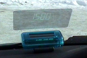
This installation will add a military jet-style digital
Heads-Up Display (HUD) to a 1997 Impreza Outback Sport. The Défi HUD has a crisp electro-fluorescent display, plus 7
LEDs on the bottom to act as a bar graph indicator. It allows the driver to keep
his/her eyes on the road. It can operate in several modes to
display speed in km/h or mph, and engine speed in rpm, or a
combination of both. I found out about it through a group buy
offer in the Impreza-RS club.
It comes in two versions, blue or red. The differences are the
display unit and LED colours. I chose the blue version, and
was rewarded with a very iMac-like blue display unit, plus very
bright blue LEDs (these
LEDs only became available in the last few years!).
The product
comes in two modules; one is the HUD display unit with an
integrated cable harness, and the other is the control unit. A
cable harness is supplied to tap into the ECU wiring, along with
four thief-style solderless connectors. Two
display films are provided to attach to the windshield. Only one
is needed, and its purpose is to provide a translucent
surface to reflect the HUD display. Without it, you will see an
additional ghost image of the HUD - the original one from the
inside surface of the glass, and the second one from the outside
surface of the glass (remember physics class?).
Materials Required:
- 1 Défi V.S.D. II (from Nippon-Seiki)
- 2"x1" set of self-adhesive hook and loop (Velcro™) fasteners (optional)
- Electrical tape (optional)
Tools Required:
- Philips screwdriver
- 10mm socket (ratchet) wrench
- Pliers (optional)
- Small flat-blade screwdriver (optional)
- Drill with 3/8" drill bit (optional)
Reference Info (for MY97 ECU*):
| Signal | Pin | ECU wire colour | HUD wire colour |
| GND | 16 or 17 | Black with red stripe | Black |
| IGN | 85 | Yellow | Red |
| RPM | 64 | Red | Green |
| Speed | 83 | Green with black stripe | Blue |
*See Lagging.com for ECU wire colour and pin information on other MY ECUs.
Wiring diagram showing pin locations on the MY97 ECU connector can
be found at Lagging.com. It
is the same as the MY98 ECU.
If you're careful, you won't need to
disconnect the battery. Just leave the keys out of the ignition
until the wires have been tapped into.
Let's Start
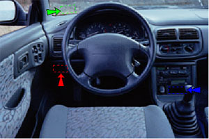
| Here is a picture of the panel before the installation
(and also before the leather
shifter modification). The display unit will be mounted in the location outlined by the green dashed box. The control module will be mounted in the diagnostic port pocket outlined by the red box. An alternative mounting location for the control module is just below the stereo, beside the 12V socket (blue dashed box). I presume this is where the ashtray used to be, before the marketing folks clued in on the healthy lifestyle revolution. Of course, you can mount the display unit anywhere else on the windshield if you like, within limitations of the optics and dashboard geometry. I'll just describe the details pertaining to my particular installation; modify/adapt as necessary! |
 |
 |
Locate the Philips screws on the lower dash panel
below the steering wheel (not shown). Remove and keep in
a safe place. Do the same with the two plastic fasteners
on the left side of the panel. Pull the
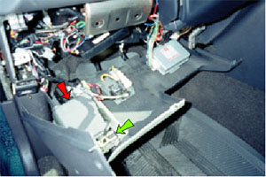
panel off. At the back of the diagnostic port pocket (red arrow), cut out a hole big enough for the control unit wires, about 3/8". Use a sharp knife to widen and clean up the hole. The green arrow shows the back side of the diagnostic port connector. |
| Thread the display unit's cable through the gap
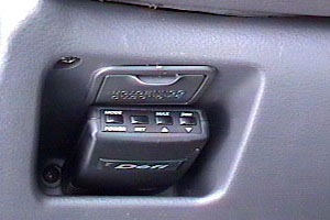
between the dashboard and the A-pillar trim (not shown). Pull through, loop the excess and hide it among the wiring harnesses. Thread the wire harness for the ECU from the driver's footwell to the passenger footwell. The best place seems to be in the gap under the ventilation assembly (red arrows in the next picture). Pass the two wires through the hole you just made, and reinstall the lower dash panel. Connect the wires to the control unit. Use the Velcro to attach the control unit to the dash panel (see picture). This installation still allows access to the diagnostic port directly in front of the control unit. Also visible in this picture are two of the screws that hold the panel in place. |
 |
|
Pull back the carpet in the passenger compartment.
Optional: I found it helpful to remove the glove box and
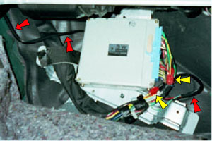
the glove box bracket to give me additional working room. Remove the large metal cover (not shown). Remove the clear plastic cover from the ECU and set in a safe place. Remove the three nuts holding the ECU bracket in place. Untie the wire tie to free the wire bundle from the floor bracket (not shown). Pull the ECU out into the middle of the passenger footwell to get access to the wires. It may be necessary to unwrap some of the electrical tape to get access to some of the wires. Note: your ECU may not look exactly like this, but you get the idea. Use the supplied red solderless connectors (yellow arrows) to tap the HUD wires into the ECU wires. It's best to do this at least 5 cm (2") away from the ECU connector, and do it in the order listed in the reference info above. Start with GND, then IGN, then the two signal wires. |
| Turn the ignition to ON, and verify that the HUD
display lights up. Then start the car, and verify that
the HUD displays the correct RPM. Drive the car half a
block to verify that the HUD displays the correct speed.
You shouldn't need to change the default ignition and
speed settings from the factory defaults. Use electrical tape to wrap the ECU wire bundle back up. Now put everything back, starting with the ECU, then the clear cover, then the metal cover. Then replace the carpet. |
|
|
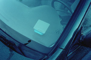
Follow the HUD instruction to apply the display film. I chose to mount the display just to the right of center from the VIN plate. This happens to be just under the unswept arc of the windshield wiper, an area of the windshield that I don't normally use to see the road with. |
|
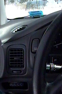
This picture shows both the display unit and the control unit mounted on
the left side of the dash. The control unit takes only a little stretch
to reach, but at night, it's operate by feel only. If the display unit is mounted against the windshield, you may need to add a piece of soft rubber between the display unit and the glass to get rid of vibration. |
|
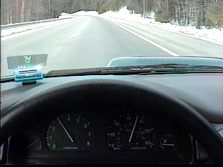 |
The speedo calibration is a little off at speeds above 65 mph (the manual mentions this). It displays 72 mph while the analog one is about 70 ½ mph. The inaccuracy becomes a bit more noticeable as speed increases after this point. Otherwise, I find the display response to be a bit faster than the analog gauge. As a bonus, you can finally see how fast you're going in reverse! |
![]()
| Back to Wayne's Impreza Outback Sport Page | © 2000 Wayne Chin. All rights reserved. | Back to top |